|
Product Details:
Payment & Shipping Terms:
|
| Material: | RO4830 | PCB Size: | 210.6mm X 54.6 Mm=2 Types =2PCS, +/- 0.15mm |
|---|---|---|---|
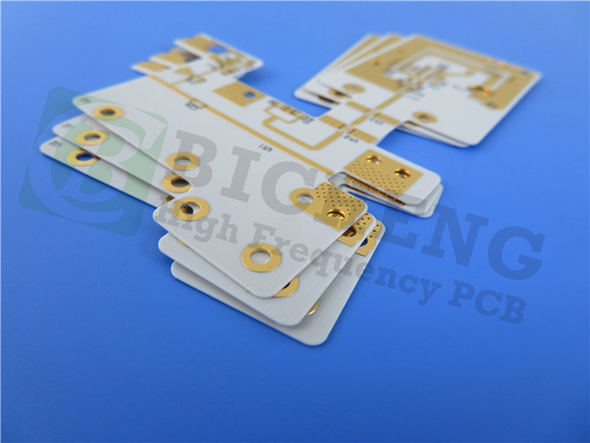
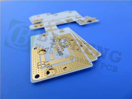
| Copper Weight: | 1oz (1.4 Mils) | Surface Finish: | Immersion Gold |
| Layer Count: | 2-layer | PCB Thickness: | 0.2mm |
| Highlight: | RO4830 PCB,Millimeter Wave PCB |
||
A Versatile Alternative to PTFE Laminates
In the rapidly evolving world of electronics, the demand for high-performance, yet cost-effective solutions has never been greater. Addressing this need, we proudly present the RO4830 PCB – a cutting-edge printed circuit board that combines exceptional performance with unparalleled affordability. At the heart of this innovative PCB is the Rogers RO4830 high-frequency laminate, a thermoset material that serves as a reliable alternative to conventional PTFE-based laminates. With a slightly higher dielectric constant of 3.2 at 77GHz, the RO4830 laminate offers a unique balance of electrical properties and cost-effectiveness, making it an ideal choice for price-sensitive millimeter wave applications.
Unparalleled High-Frequency Performance
One of the key features that sets the RO4830 PCB apart is its exceptional insertion loss of just 2.2 db per inch at 77GHz. This remarkable performance is achieved through the use of LoPro reverse treated copper foil cladding, which contributes to the laminate's excellent high-frequency characteristics. Designed for demanding millimeter wave applications, the RO4830 PCB is well-suited for use in 76-81 GHz automotive radar sensors.
| Property | Typical Values [1] RO4830(TM) |
Units | Condition | Test Method | ||
| Dielectric Thickness | ||||||
| 0.005” | 0.0095” | |||||
| Dielectric Constant, εr Design | 3.24 | 3.24 | - | 77 GHz | microstrip differential phase length | |
| Transmission Line Loss | 2.2 | 1.8 | dB/in | 77 GHz | microstrip differential phase length | |
| Dissipation Factor, tan δ | 0.0033 | 0.0032 | - | 10 GHz | split-post dielctric resonator | |
| Thermal Coefficient of εr (z direction) | -30 | -30 | ppm/°C | -50°C to 150°C | IPC-TM-650 2.5.5.5 | |
| Dielectric Strength | 78.7 | 59.1 | kV/mm | 48 hrs @ 50°C | IPC-TM-650, 2.5.6.2 | |
| 2000 | 1500 | V/mil | ||||
| Water Absorption | 0.15 | 0.13 | % | D-48/50 | ASTM D570 | |
| Peel Strength after Thermal Stress | 0.67 | 0.67 | N/mm | 18 micron reverse treated EDfoil |
IPC-TM-650 2.4.8 | |
| 3.8 | 3.8 | lbs/in | ||||
| Flammability Rating | V-0 | V-0 | - | C-48/23/50 | UL94 | |
| Dimensional Stability |
MD | -1.8 (-1.8) |
-1.5 (-1.5) | mm/m (mils/in) | 4 hrs @ 105°C | IPC-TM-650 2.4.39A |
| CMD | -1.8 (-1.8) |
-1.6 (-1.6) | ||||
| Decomposition Temperature | 408 | 412 | °C | - | ASTM D3850 | |
| Time to Delamination (T288) | >30 | >30 | minutes | with Cu | IPC-TM-650, 2.4.24.1 | |
| Lead-Free Process Capable | YES | YES | - | - | - | |
| Thermal Conductivity (calculated) | 0.45 | 0.47 | W/mK | 50°C | Through-plane calculation with series mixing rule |
|
| CTE | x,y | 23 | 21 | ppm/°C | 0 to 150°C | IPC-TM-650 2.4.41 |
| z | 110 | 83 | ||||
Optimized for Automotive Electronics
Its optimized filler, resin, and glass composite system, combined with a UL 94 V-0 flame retardant rating, ensures superior thermal and mechanical stability, making it an ideal choice for mission-critical automotive electronics.
Reliable and Consistent Construction
The PCB's construction features a 2-layer rigid design, with 35 μm copper layers on both the top and bottom. The core material, measuring 0.127 mm (5 mil) in thickness, delivers exceptional dimensional stability and consistent dielectric properties across the sheet, ensuring reliable performance even in the most demanding environments.
Cost-Effective Fabrication and Accessibility
In terms of fabrication, the RO4830 PCB can be produced using standard FR-4 processes, making it accessible and cost-effective for a wide range of manufacturers. This versatility extends to the PCB's physical dimensions, which are available in two variants measuring 210.6 mm x 54.6 mm, with a tight tolerance of ±0.15 mm.
Rigorous Quality Assurance
To ensure the highest quality standards, the RO4830 PCB undergoes rigorous testing and inspection procedures. With a minimum trace and space of 4/5 mils, a minimum hole size of 0.3 mm, and 100% electrical testing prior to shipment, customers can be confident in the reliability and precision of this PCB.
| PCB Material: | Hydrocarbon/ Ceramic/ Spread Woven Glass |
| Designation: | RO4830 |
| Dielectric constant: | 3.24 |
| Dissipation factor | 0.0033-0.0032 |
| Layer count: | Single Sided, Double Sided, Multi-layer PCB, Hybrid PCB |
| Copper weight: | 1oz (35µm), 2oz (70µm) |
| Dielectric thickness | 5mil (0.127mm), 9.4mil (0.239mm) |
| PCB size: | ≤400mm X 500mm |
| Solder mask: | Green, Black, Blue, Yellow, Red etc. |
| Surface finish: | Immersion gold, HASL, Immersion silver, Immersion tin, ENEPIG, OSP, Bare copper, Pure gold etc.. |
![]()
Unparalleled Benefits for Manufacturers
Beyond its technical specifications, the RO4830 PCB offers a range of benefits that make it an attractive choice for manufacturers. Its significantly reduced oxidation resistance and excellent laser drilling performance contribute to a streamlined manufacturing process, while the overall cost savings compared to PTFE laminate options make it a financially prudent investment.
Unlock the Power of Millimeter Wave Technology
Whether you're working on cutting-edge automotive radar sensors, advanced smart electronics, or any other millimeter wave application, the RO4830 PCB from Rogers is the reliable and cost-effective solution you've been searching for. Experience the power of this innovative technology and take your project to new heights of performance and efficiency.
Contact Person: Ms. Ivy Deng
Tel: 86-755-27374946
Fax: 86-755-27374848